Most people starting out leaning about programmable logic controls (PLC) are taught all about discrete input and outputs. Data is received from devices such as push-buttons, limit-switches etc. and devices are turned on such as motor contactor, lights, etc. Discrete input and output bits are either on or off. (1 or 0)
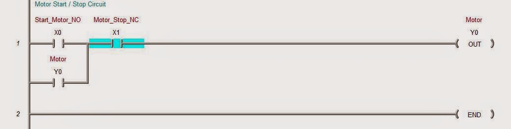
The following program will show a motor control circuit stop start.
Motor off:

Analog inputs
Common input variables for analog are temperature, flow, pressure, etc. They are converted to an electrical signal into a PLC analog input. Standard electrical signals are 0 - 20 mA, 4 - 20 mA, 0 - 10 volts DC, -10 - 10 volts DC.
Note: It is recommended that a 4 - 20 mA signal is best. If voltage is required, a resistor can be added to get a voltage input.
Analog outputs
Common output variables for analog are speed, flow, pressure, etc. They are converted from a word in the PLC to the output of the analog. The range of signal is then outputted to the device to control the position, rate, etc. Standard electrical signals to the device are 4 - 20 mA, 0 - 10 volts DC, -10 - 10 volts DC.
Both Analog Inputs and Outputs use words to determine the signal going to or from the device.
Example: 4 - 20 mA current Input - 8 bit resolution
4 mA = 000000002 = 0016
20 mA = 111111112 = FF16
Example: 4 - 20 mA current Output - 8 bit resolution
0016 = 000000002 = 4 mA
FF16 = 111111112 =20 mA
For a review of numbering systems, follow the link below:
What everyone should know about PLC numbering systems
No comments:
Post a Comment